![]()
|
|
|
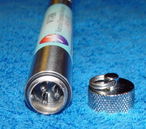
| Cap and Communication
socket There is a screw on knurled cap on the top of the WT-HR logger. This has a suspension ring that can be used to suspend loggers down wells or pipes. The cap is removed to attach a download cable and recover data. |
|
|
Logger section The logger section of the WT-HR is a 20mm diameter stainless steel tube 170mm in length. There is a three pin communication socket at one end and a 16mm long, 6mm diameter threaded rod at the other. This threaded rod has a cable running through it. The cable has a temperature sensor on the end for monitoring water temperature |
| Probe and Logger to probe
connection The Probe consists of a outer tube and an inner rod The Inner Rod screws on to the 16mm long, 6mm diameter threaded rod protruding from the Logger. The temperature sensor with cable runs down the center of the inner tube so that the temperature sensor sits at the bottom of the inner tube. The Outer Tube screws directly onto the logger |
|
|
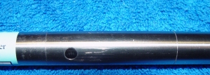
Top Breather Hole and
Maximum Datum Mark The distance from the top of the probe to the Maximum Datum Mark is 75mm on all WT-HR loggers WT-HR 250 and 500 is 70mm WT-HR 1000, 1500 and 2000 is 75mm |
| Maximum and Zero Datum
Marks WT-HR 250 Zero to Maximum Datum is 250mm WT-HR 500 Zero to Maximum Datum is 500mm WT-HR 1000 Zero to Maximum Datum is 1000mm WT-HR 1500 Zero to Maximum Datum is 1500mm WT-HR 2000 Zero to Maximum Datum is 2000mm |
|
|
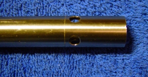
Bottom Water Entry Port
and Zero Datum Mark The distance from the Zero Datum Mark to the bottom of the probe: WT-HR 250 and 500 is 35mm WT-HR 1000, 1500 and 2000 is 75mm |
![]()
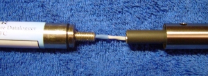
Removing the Probe from the Logger
| Removing the Logger from
the Outer tube Hold the outer tube and unscrew the logger anti clockwise. When the logger is free of the outer tube separate them by about 30mm by pulling the Logger and inner rod up out of the outer tube. Note the small black O-ring between the logger and the outer tube. |
|
| Removing the Inner rod
from the Logger Now hold the Inner Rod between the fingers of one hand and screw the logger anti-clockwise off the inner rod. When the logger is free, withdraw the cable and temperature sensor from the inner tube. Keep the Logger, Outer Tube and Inner Rod together. They have been calibrated together and if a logger is connected to a different outer or inner it should be recalibrated. |
|
| Removing the Inner Rod
from the Outer Tube Be very careful of the black insulating covering on the outside of the inner rod. This covering is very delicate and will cause the WT-HR to malfunction if it is damaged. There is a plastic spacer attached to the bottom of the inner rod. The inner rod can be withdrawn from the outer tube being careful not to scrape the black insulation covering on the inside of the outer tube. |
|
| Reconnecting the Probe to
the Logger Carefully slide the inner rod down into the Outer tube. Feed the temperature sensor with cable down into the inner rod. Screw the logger onto the inner rod. Check that the small black O-ring is sitting in the threaded end of the logger.Screw the outer tube onto the logger. |
![]()
| Mounting The Logger should be mounted vertically.If the logger is in a flowing river the flow causes water to rise up on the logger giving high readings so in a river with strong flow the logger should be mounted inside a plastic pipe with holes drilled in it - this way the logger reads the real height of the river. Make sure the logger is mounted in such a way that the bottom holes (water entry ports) do not get blocked but mud or stones. |
|
| Maintenance The water height probe should be cleaned every six months or more frequently in dirty, salty or polluted water. Remove the probe from the logger as detailed above. Clean the outer tube with hot water and a lint free cloth. Carefully clean the inner rod by hand rubbing warm water (30degC or less) up and down its length. Check that no water has found its way into the inner tube. If it has, dry throughly before reattaching the inner tube to the logger. |